In the first installment of this series, I mentioned a couple of times that the track geometry of LEGO® Trains is unique from most other model trains, and sometimes very limiting. Let's delve further into what the phrase "track geometry" means.
There are five pieces available directly from LEGO® for your train track needs: a 16-stud straight piece, a 16-stud curved piece with a radius of 40 studs (measured from the center of the track), a left and a right switch (~32 studs long each), and the 4-stud-long flex track piece. The rails are spaced six studs apart, with an extra stud on the ties, to make each track section 8 studs wide. Switches are of course, wider, but the dimensions of the individual routes are still 8 studs wide.
This photograph shows the whole range of official LEGO® train track parts. On the far left is a standard curve, and on the far right is a standard straight. The bottom center shows one piece of flexible track, and the top center shows four pieces of flexible track connected together, equaling the length of the curve and straight track, but with the ability to shift into unusual shapes. Also shown is one left-hand switch (set for the diverging route) and one right-hand switch (set for the straight route).

The five track pieces as they appear in Track Designer.

The five track pieces as they appear in Bluebrick.
Other track pieces are available from third-party manufacturers, or one can modify the track themselves, but for the moment we'll focus on these five 'official' parts. You will find that the 16-stud straight can fit on a 16x16-stud baseplate, with a 4-stud margin on either side. In a similar vein, a quarter-turn of curved track will fit on a 48x48-stud baseplate. When you attach a curved track to the diverging route of a switch, you will see that the following straights create parallel tracks, spaced 8 studs apart. Now, remember from part 1 when I said I was adding a 4-stud border around our circle layout to make it measure an even 30x30 inches(76.2cm x76.2cm)? A 16-stud-square baseplate is 5 inches by 5 inches (12.7cm x 12.7cm)! Let's put all this information in a picture for a clearer understanding:
On the left, a full circle of 16 straight tracks fits on a grid of 5"x5" squares, or 16x16-stud baseplates, for a total of 30"x30". In the top center, a piece of straight track fits on a 16x16 stud square baseplate, with a 4-stud margin on either side. On the top right, a 180-degree turn of 8 curved tracks is the same width as three 32x32 stud (10"x10" or 25.4x25.4cm) baseplates, but we need an extra 16 studs vertically to completely cover the ends of the turn. In bottom right, a quarter-turn of curved track fits on a 48x48-stud baseplate (15"x15" or 38.1cmx38.1cm) with a 4 stud margin between the outer edge of the curve and the corner of the baseplate. Finally, a switch with a curved piece splits into two parallel tracks spaced 8 studs apart.
The point of all this is that LEGO® tracks adhere to a grid system, which can make planning a layout very easy. Now that we've established this grid, let's look at a few track arrangements that do not fit on the grid, and some space-saving techniques that DO fit on the grid.
New layout builders may find that their creative arrangements of curved track do not meet up properly when one is trying to close their loop (though the advent of flexible tracks can help alleviate this issue), and this is usually due to a funky arrangement of curves not aligning to the grid.
Note that the examples on the left and right come close, and possibly a piece of flex track or two may help slightly, but the arrangement in the center will not work on the grid at all.
It is also worth pointing out at this time that model trains generally do not like opposite-direction curves back-to-back (these are defined as S curves, as they resemble the shape of the letter). Some of the LEGO® Train sets can handle it, but heavier pieces of rolling stock (read: trains that you built yourself) will bind on the curves or possibly derail. If you're going to put curves in opposite directions in a row, it's best to put a piece of straight track in between them, or at least a couple of sections of flexible track.
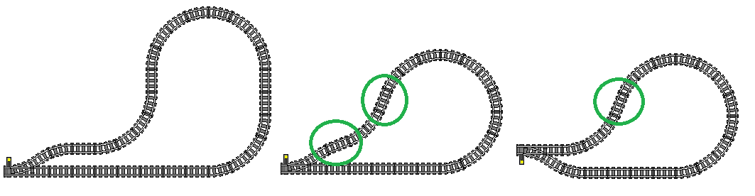
Putting a piece of straight track in between opposite directions of curves brings us to a handy trick to save space and pieces in our layouts: one straight track can equal two curved tracks. Observe the following:
In the first example, a piece of straight track is placed between the two opposing-direction curves. A good practice. In the second example, there is no straight track between the opposing-direction curves. This could cause a derailment. In the last example, a piece of straight track has been substituted for the spot where the two curved tracks met, so each curve section is only three curved tracks long. We've also managed to save 32 studs (10" or 25.4cm) of vertical space by shortening this S-curve.
We've stated a couple of times that a curved track must be attached to the diverging route of a switch to align both routes to be parallel on the grid. Here's the info straight from LEGO®'s mouth, taken from a leaflet that came with the World City line of trains in the early 2000s:
But let's suppose you want your diverging route to curve off in a different direction. Again, we can replace two curved tracks with one straight track and save on parts and space:
We see in the first example a straight piece in between the two opposing-direction curves. The second example shows no straight piece and therefore an undesirable S-curve, and the third example has an even worse S curve by putting an opposite-direction curved piece right after the switch. A couple lengths of flex tracks could potentially align the track back to the grid, but the S curve between the switch and curved piece could cause a derailment. The fourth example shows a straight piece in place of the two curves, saving us some space and still aligning to the grid.
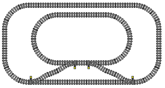
A good example of applying this information would be the turnaround loop. In the first section of this series, the return loop was built without using this curved-track shortcut. Here is the return loop in both fashions: once with the switches and curves set up in a standard fashion, and two arrangements with the one-straight-for-two-curves trick:
We don't need the grid to see that a LOT of space was saved by the one-straight-for-two-curves trick!
Let's look at one more example of the application of this track trick before we apply our knowledge to layout planning. In the first installment of this series, we only looked at single-track railroads, or track plans with only one main route. If one wants to run multiple trains at once without interference, it is advised to have two independent loops of track, or loops that do not share any portion of their route.
These two circles of track are completely independent from one another. The grid is provided for convenience.
While having two independent loops for running trains is nice, one might wish to switch a train from the inner loop to the outer loop, or perhaps interchange some cars between the trains on each loop. This is where a "crossover" comes in. A crossover is a pair of switches linking two independent sections of track.
In this photograph from Pittsburgh, PA, we can see two crossovers directly in the shadow of the bridge, linking the outer tracks with the inner tracks. The train is rolling over two more crossovers linking the inner two tracks, and beyond that we can see two more crossovers linking the inner tracks with the outer tracks in the opposite direction.
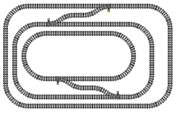
We COULD simply link the two diverging routes of our switches and connect our independent loops that way, but once again, our layout wouldn't perfectly conform to the grid. Better to use two curved tracks (one for each switch, so the diverging route becomes parallel to the main route) with a straight track in between, or just one straight track to link those two switches and conform our layout to the grid.
The first example is what NOT to do: because the diverging routes of the switches are oblique without curved tracks to complement them, the outer loop of this layout is completely misaligned from the grid, and the outer track is too close to the inner track along the top of the plan. In the second and third examples, a properly aligned crossover (either with two curves and a straight, or one straight substituting for two back-to-back curves) means that BOTH loops align perfectly to the grid. Note that in each case, both switches are left-handed switches. Also note that a train traveling clockwise on the outer loop must reverse through the crossover to reach the inner loop, and vice-versa.
At this point, one might beg the question: "What's so important about lining up to the grid? Those two independent loops still fit together, even if they're not aligned perfectly to the 5"x 5" (12.7cm x 12.7cm) grid! What's stopping me from building something like that?" The short answer is: nothing! If you're able to make a track layout work without aligning your tracks to the grid, more power to you! If you're just building tracks all over the living room floor for an afternoon of fun, then the grid doesn't concern you all that much, which means most of the information thus far is simply to inspire ideas and help troubleshoot derailments and other minor issues. The point of the grid is that it's an easy reference point to ensure all tracks will fit together, AND, as we will see in future installments of this layout planning series, aligning to the grid makes it easier to lay out streets and buildings alongside our tracks.
We will look at one more type of railroad track arrangement and how we can use our straight-track-for-two-curved-tracks space-saving technique to make it easier, but first, here are a few more examples of crossovers between tracks. We will drop the grid from the example images for the moment.


So far, the only method we've seen for turning a train around is the reversing loop. Novice train enthusiasts may be familiar with the turntable, but these are difficult to build in LEGO®, and are usually just for the locomotive; not practical for turning an entire train. This is where the Wye comes in. Named after the letter Y for its shape, this track arrangement requires three switches to work. A good prototype example can be found at the Tennessee Valley Railroad Museum in Chattanooga:

This satellite photo shows the wye at Grand Junction Station. A train enters from the lower left, and pulls up to the station along the top-left leg of the wye. After the passengers are loaded, the train pulls forward of the switch at the top center of the photo, then reverses along the curved track obscured by trees. The tail track in the lower right is just barely long enough to fit a locomotive and three passenger cars. Once the train is clear of the switch adjacent to the road crossing, it pulls forward along the lower leg of the wye, past the sidings of equipment on display, and returns to the track it came from in the lower left, now traveling in the opposite direction.
A wye can be used for turning trains, or to connect a branch line that is perpendicular to the main line. We can build a wye using three of our switch track pieces. Note that if you are using the old metal track instead of the modern plastic track, a wye will cause a short-circuit. We'll look at how to prevent short-circuits in the future. Here are three examples of a wye in LEGO®, two of which use the one-straight-for-two-curves trick that has been a main feature of this installment of the track planning series:

The first example shows the basic properties of building a wye in LEGO®, and the second two examples show the use of the straight-for-curve trick.
We'll close part 2 of our LEGO® Train Track Planning series with a few examples of layouts using wyes. Part 3 of this series covers the use of third-party track pieces. If you would like to be notified when the next installment of this series is posted, please follow my Facebook page or my Instagram feed. Thanks for reading!


